Installation and Wiring-Overview
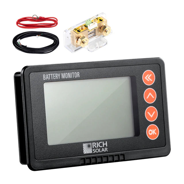
The RS-BM500 shunt should be mounted as close to the battery as possible, and the remote display is intended to be mounted on a wall.
Recommended Tools
- Wrench
- Drill
- Jigsaw
- 2 ring terminals of appropriate size for battery cable
- Crimp tool for ring terminals
Wiring Diagram
The following wiring diagram will be referenced in the next section.

Installation
- Before doing anything, disconnect all wires from the negative side of the battery.
- Cut the negative cable for the battery and crimp on new ring terminals. Alternatively, use a new wire of appropriate gauge to carry the full current demand of your system.
- Install the shunt as shown in the wiring diagram above.
Note: The negative terminal of the battery must connect directly to the “B-" side of the shunt, and there should be no other connections to the negative terminal of the battery for accurate measurements.
- Use the B+ wire included in the package to connect the B+ terminal of the shunt to the positive side of the battery.
Note: Do not stack smaller terminals under large ones.
- Connect the shunt to the remote display using the included shielded cable.
Mounting the Remote Display
- Plan the location of your remote display and keep in mind there is a cable that needs to route all the way to the shunt.
- Drill a hole in the center of the planned location and use the jigsaw to cut a hole according to the following picture.
- Connect the shielded cable to the shunt and route it such that you can bring it through the hole.
- Connect the shielded cable to the remote and snap the remote into place.
Specifications
-
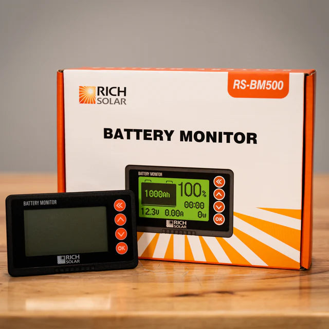
Model: RS-BM500
-
Battery Voltage Range: 8-120V
-
Working Dissipation: 10mA
-
Standby Dissipation: 1mA
-
Capacity Accuracy: ±1.0%
-
Voltage Accuracy: ±1.0%
-
Current Accuracy: ±1.0%
-
Backlight On Current: 80mA
-
Capacity Setting Value: 0-500A
-
Current Range: 0.1-9999Ah